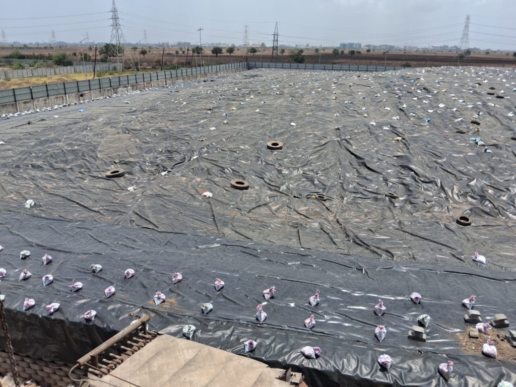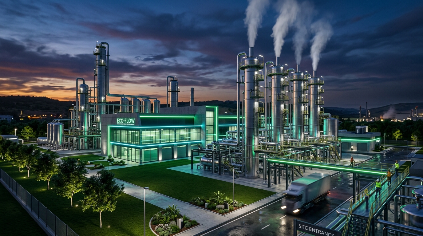

Our Common TSDF is designed strictly according to CPCB and MoEFCC guidelines for hazardous and industrial solid waste management. It incorporates multi-layered engineered double composite liner systems, continuous leachate extraction, and a dedicated chemical stabilization laboratory.
Engineering standards compliant with CPCB Criteria for Hazardous Waste Landfills
| Parameter | Design Specification |
|---|---|
| Annual Capacity | 100,000+ Metric Tonnes / Year |
| Cell Liner System | Double HDPE Geomembrane (1.5 & 2.0 mm) + Geotextile |
| Clay Barrier | 900 mm Compacted Clay (Permeability < 1×10⁻⁷ cm/s) |
| Waste Classes Accepted | Schedule I, II, & III Hazardous and Non-Hazardous Solid Waste |
| Manifesting & Tracking | Automated XGN Portal E-Manifest & Weighbridge Barcode |
| Post-Closure Plan | 30-Year Long-Term Environmental & Leachate Monitoring |
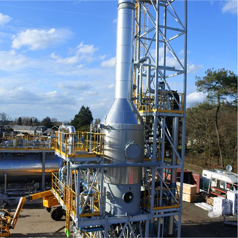
The Stripper Column system acts as the critical frontline pre-treatment unit for high-COD industrial wastewater containing volatile organic compounds (VOCs), low-boiling solvents, ammonia, and light hydrocarbons. By extracting these volatiles upstream, it prevents fouling in MEE evaporators and ensures maximum energy efficiency.
Engineered for High-VOC, Multi-Component Solvent Wastewater
| Parameter | Design Specification |
|---|---|
| Operating Capacity | 500+ KLD Continuous Stripping Throughput |
| Stripping Media | Direct Low-Pressure Steam / Heated Air Stripping |
| Column Internals | Structured High-Efficiency SS316L / PVDF Packing |
| Feed COD Range | Up to 100,000 mg/L COD |
| Target Volatiles | Methanol, IPA, Toluene, Acetone, Hexane, Pyridine, Dichloromethane |
| Vapor Treatment | Dual Condensers + Chilled Brine After-Cooler + Carbon Bed |
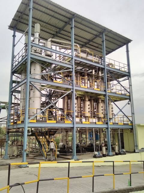
Our Common MEE facility is the technological core for treating recalcitrant, high-TDS wastewater streams. Utilizing a quadruple-effect thermodynamic cascade with forced circulation calandrias, it concentrates dissolved solids up to saturation limits while recovering high-purity process water for Zero Liquid Discharge (ZLD).
Industrial Scale High-TDS Thermal Evaporation Plant
| Parameter | Design Specification |
|---|---|
| Total Plant Capacity | 1,500+ KLD (Kiloliters / Day) Multi-Stage Grid |
| Configuration | Quadruple Effect (Falling Film + Forced Circulation) |
| Operating Vacuum Range | -0.85 to -0.92 bar (Low-temperature boiling) |
| Feed TDS Range | 20,000 to 150,000 mg/L |
| Concentrated Output | 40% to 50% w/w TDS Slurry (Fed to ATFD) |
| Distillate Recovery | 85% - 90% (TDS < 100 mg/L, COD < 250 mg/L) |
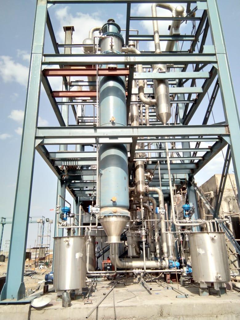
The Agitated Thin Film Dryer (ATFD) is the indispensable bridge between concentrated MEE liquid effluent and final solid salt disposal. Utilizing high-speed rotor blades within a steam-jacketed cylindrical body, it mechanically spreads slurry into an ultra-thin turbulent film, driving off remaining moisture to produce free-flowing crystalline salt cake.
Continuous Mechanical Thin-Film Evaporation & Solidification
| Parameter | Design Specification |
|---|---|
| Throughput Capacity | 300+ Metric Tonnes / Day of Concentrated MEE Slurry |
| Heating Jacket | High-Pressure Steam Jacket (3.5 to 5.0 bar g) |
| Construction Material | SS316L Contact Parts / Titanium Grade 2 for Chlorides |
| Rotor Type | High-Speed Dynamic Balancing with Hinged Scraper Blades |
| Final Product Moisture | < 5.0% w/w Residual Moisture |
| Vapor Recovery | Integrated Surface Condenser with Vacuum Ejector |
Our industrial Spray Drying facility provides rapid, single-step thermal atomization drying for high-COD, high-TDS liquid effluent streams that are unsuitable for conventional heat exchangers. Liquid feed is pulverized into micro-droplets inside a co-current hot gas drying chamber, achieving instant moisture flash vaporization and producing dry inert powder.
Industrial Atomization Chamber & Multi-Stage Air Scrubbing
| Parameter | Design Specification |
|---|---|
| Water Evaporation Rate | 5,000+ kg/hr Continuous Water Evaporation |
| Inlet Air Temperature | 300°C – 380°C (Natural Gas / Clean Fuel Fired Air Heater) |
| Outlet Air Temperature | 105°C – 120°C |
| Atomizer Speed | 12,000 – 18,000 RPM Variable Frequency Drive |
| Air Pollution Control | Cyclone Separator + Pulse-Jet Bag Filter + Multi-Stage Wet Scrubber |
| Stack Emission Standard | Particulate Matter < 50 mg/Nm³ (Connected to GPCB OCEMS) |